Viagra gibt es mittlerweile nicht nur als Original, sondern auch in Form von Generika. Diese enthalten denselben Wirkstoff Sildenafil. Patienten suchen deshalb nach viagra generika schweiz, um ein günstigeres Präparat zu finden. Unterschiede bestehen oft nur in Verpackung und Preis.
Cyphynets.lums.edu.pk
Road Traversability Analysis Using Network Properties of Roadmaps*
Muhammad Mudassir Khan1, Haider Ali2, Karsten Berns3 and Abubakr Muhammad1
Abstract— Traversability analysis is an important aspect of
its traversability which is sometimes not possible. To avoid
autonomous navigation in robotics. In this paper, we relate
traversing the terrain to find its traversability, exterioceptive
the idea of traversability to safety and ease of road usage
techniques use long range sensors like vision, laser, ultra-
by defining a novel sensor-data driven metric called Road
sound etc. to measure traversability of a terrain. [6] and [1]
Traversability Index (RTI). The RTI translate the geometricinteraction of vehicle with road into a distance modulated index
used vision based features to classify terrain into a number of
that can be used as advice for a human driver or an autonomous
classes like grass, asphalt, gravel, etc. [10], [8] and [11] use
agent intending to traverse a particular road segment using a
LiDAR data for terrain classification into ground, rocks, and
specific vehicle. We present a framework in which 3D sensor
vegetation. One can also envision the collection of such data
data is converted into a road model, which in turn is converted
using aerial platforms, by which the issue of traversability
into a roadmap based motion planning graph to representthe underlying configuration space. The RTI is defined as a
of the scout vehicle becomes irrelevant [14].
function of the roadmap by axiomatically satisfying all required
Once a map has been obtained, determining traversability
properties of road traversability. We have tested our algorithmic
of the terrain is the next task. Many approaches like [2]
framework on simulated scenarios to explore safety; and real-
use only terrain data to find local traversability. They find
world data sets to discover aspects of traversability for vehicles
features like roughness, slope, discontinuity and hardness
of various types. Experimental results show that RTI is apractical tool that reveals information that may be hidden to
of the terrain and try to infer traversability from these
human inspection or other methods of assessment that do not
features. They do not analyze whether a vehicle of certain
explicitly model a vehicle.
size and kinematics can traverse the terrain or not. Otherapproaches like [14], [12] and [13] uses vehicle model along
with terrain data for traversability analysis. They use explicit
To traverse a road, both autonomous vehicles and human
motion planning techniques to find a feasible path in a given
drivers need to detect obstacles and find navigable paths in
scenario. However, to give answers to questions of road
real-time. The driver proceeds with the belief that at least
safety or general traversability posed above, one needs to
some feasible path will always be available to take the vehicle
capture exhaustively all possible paths to allow the choice
closer to its destination. If for some unforeseen reason, a road
of the driver in enumerating all possible scenarios while
becomes non-traversable, the vehicle gets stuck on the road.
negotiating a particular terrain. Moreover, the linear structure
To prepare for such situations, a more desirable approach can
of road like pathways requires a moving-window approach
be to predict before-hand whether the road conditions allow
in which the notion of a continuous forward movement is
passage for particular types of vehicles. And if so, what is
captured. This may or may not coincide with typical notions
the relative level of confidence in allowing a certain vehicle
of navigable space in terrain traversability.
to go forward? Due to advances in perception and motion
Given the 3D geometric properties of a road patch cap-
planning techniques, such an approach is not only relevant
tured by a perception system and those of a particular
for standard road safety analysis but can also be extended to
vehicle, we seek to verify in this paper whether the vehicle
off-road scenarios, disaster situations and unpaved pathways.
can traverse through it in the forward direction. If so, what
To determine the traversability of a terrain, proprioceptive
is the difficulty level of the vehicle's traversability? We
techniques have been used to analyze the internal state of
propose a sensor data driven Road Traversability Index (RTI)
the vehicle using on board sensors like vibration, IMU,
which assigns a scalar value to each road patch along the
wheel slip, etc. Brooks et al. [3] used vibration analysis
length of the road. We deploy a scout vehicle to collect
to classify terrain into sand, gravel and clay. Leppanen et
the sensor data on which the index is computed offline.
al. [9] determined the quality of terrain, while driving with
Once the RTI is computed as a function of distance along
a mobile robot. Problem with proprioceptive techniques is
a particular road segment, it can be shared with a driver
that the vehicle has to traverse a terrain in order to measure
or autonomous vehicle to make it aware of the relative
*This work has been supported by a LUMS Faculty Initiative Fund (FIF);
difficulties of traversing a particular road. It can provide non-
research visit support provided to H. Ali under the PPQP Scheme of Govt.
obvious answers to traversability questions. For example, a
of Pakistan; and a grant awarded to TUKL and LUMS under a DAAD
particular road segment may be traversable by only one type
German-Pakistani exchange program.
1M. M. Khan and A. Muhammad are with the Dept. of Electrical
of vehicle and not by another. To appreciate this, consider
Engineering, LUMS, Pakistan {10060013, abubakr}@lums.edu.pk
the scenario depicted in Fig. 1, where an obstacle on the road
2H. Ali is a senior researcher at Robotics and Mechatronics Center,
(e.g. a pit) is so wide that a smaller vehicle may not be able to
German Aerospace Center (DLR), Germany
[email protected]
3K. Berns is with the Dept. of Computer Science, TU Kaiserslautern,
pass but a larger vehicle may be able to negotiate the obstacle
by placing tires on opposite sides of the pit. In a disaster
(a) Small vehicle can traverse but large vehicle can not.
(b) Large vehicle can traverse but small vehicle can not.
Fig. 1: Example scenario where obstacle position on road can effect vehicle's traversability for different types of vehicles.
In (a) a small vehicle can traverse the road by keep itself towards the edge of the road while the large vehicle can nottraverse it. In (b) the scenario is totally opposite. Now large vehicle can traverse the road by placing its tires on the sidesof the obstacle. While small vehicle can not traverse the road any more because of not enough space.
scenario, a paved road segment once considered safe for all
will be captured by the narrow passage shown in right image.
types of vehicles may now be usable for only certain types. In
Note that all paths present in the right image are already
a developing world situation, a village semi-structured road
present in the obstacle free scenario. Therefore, the presence
may have deteriorated to the point that only certain types
of obstacles has limited the freedom in choosing the paths
of vehicles can use it. Answers to such questions cannot be
joining both ends. However, measuring this freedom is not
given by qualitative manual inspection of the road only.
straight forward. The range of possibilities manifested by
The paper is organized as follows. We first define the no-
vehicle kinematics and its geometric footprint forces us to
tion of road traversability and motivate the need for an index
work in the configuration space rather than the ambient
in Section II. Next, we present the framework under which
space of the road plane. Moreover, dealing directly with
we compute this index in Section III. We show axiomatically,
the underlying continuous space makes the problem of path
how our definition of a Road Traversability Index (RTI)
enumeration algorithmically intractable. We therefore take
defined on roadmap graphs satisfies the requirements of a
the following approach.
good metric for our envisioned applications. In Section IV,
The road model is built by a 3D perception system that
we summarize results from application of our framework
digitally captures the ambient space geometry in front of
to various data-sets, both simulated and real. The paper is
the scout vehicle. From this road model, standard roadmap
concluded by a discussion in Section V.
based sampling techniques are used to get a dense graph the-oretic representation of the underlying configuration space.
II. MEASURING ROAD TRAVERSABILITY
Traversability can now be studied on this roadmap graph to
Traversability is a broadly used term and it is interpreted
infer the desired properties of the underlying configuration
based on the context and application. Generally, it is defined
space. In Section III, we formally define a function RTI
as the safety of a vehicle traversing a terrain while obeying
Γ : G → [0, 1] which takes the roadmap graph G extracted
some constraints. Traversability is also referred by different
from the road model as an input and outputs a real value,
names depending upon the context in which it is used [12].
with 0 indicating that the road is not traversable by the
In this paper, we define it as a measure of the free space
vehicle, 1 meaning the maximum possible traversability and
available for a vehicle to traverse from one end of the road
a value in between meaning relative traversability. Note
segment to the other. This may be captured by the freedom
that such traversability has to be reported for each road
in choosing paths on the road joining start positions in one
segment inspected by the scout and therefore the RTI will be
end to goal positions at the other end.
computed as a distance modulated function of each segment
In order to elaborate on this concept, refer to Fig. 2.
analyzed along the length of the road.
The left image shows a single representative path (traced by
It is also important to comment on the current limitations
the center of a vehicle) from one end of the road segment
of this approach. Note, that in this geometric model two
to the other. The center image shows the collective image
aspects are still missing. First, there is no inclusion of a road
of all such paths. Now, if obstacles are introduced, the
contact model whereby a surface that may look geometrically
traversability of the vehicle on the road will decrease and
traversable may not be so due to improper tire grip and
Narrow Passage, Limited Paths
Fig. 2: Graphical representation of traversability of a road segment. Green is traversable road area, which is restricted byobstacles, resulting in a narrow passage shown by red arrow (right).


other factors. This however is a limitation common to all
fitting to extract its parameters. RANSAC is used to extract
exterioceptive methods. In our case, if such proprioceptive
coefficients (a,b,c,d) in plane parametric equation a · x + b ·
data is available, it can be easily incorporated into labelling
the obstacles based on both geometry and surface type. Sec-
Obstacles: Our traversability is based on the assumption
ondly, only geometric interaction of vehicle with terrain have
of non-traversable static obstacles. Both negative obstacles
been modelled in this paper. Traversability of many obstacles
(ditches and potholes) and positive obstacles (speed breakers,
depend on vehicle kinematics and dynamics (e.g. at different
traffic signals, walls, footpaths etc.) are assumed to be present
speeds, weight etc.). Again, the current framework provides
on the road.
the framework whereby configurations can be upgraded to
full dynamical states, when computing the roadmaps. Weleave such extensions to a future work. In this paper, the
A subset of geometry based approaches uses vehicle model
focus is on geometric interaction of vehicle and road.
in order to find its traversability. Vehicle model consist of anumber of parameters that describe the shape and physical
properties of the vehicle. The parameters of the vehicle are
The methodology as given in Fig. 3 is used to find the
used to generate vehicle model and the model is used to find
traversability of a road patch. First road 3D data is recorded
the interaction of the vehicle with terrain. The parameters
using any range sensor and it is preprocessed to remove
of the vehicle used for traversability analysis are given in
outliers, crop unwanted region and down sample the data
Table I. Holonomic and non-holonomics constraints are used
to reduce computation time. Terrain surface in the 3D data
while generating roadmap graph.
is find using a terrain model. Using terrain model and vehicle
TABLE I: Various vehicle parameters used for traversability
parameters, a number of different vehicle configurations Qi
are generated on the road surface. Each configuration isassigned a valid flag which is true if the configuration is
collision free and false otherwise. A roadmap graph G =
Width of the vehicle
Length of the vehicle
(V, E) is generated using these configurations, where each
Height of the vehicle from
node vi ∈ V is configuration qi ∈ Q and each edge
Wheelbase: distance between
i, vj ) ∈ E means there is a collision free path from vi
front and rare axle
to vj. By studying the properties of this roadmap graph, we
Track: distance between cen-
can find interesting information about the traversability of
ter of rare tires
the road. Below we explain all the steps in details.
Ground Clearance of Vehicle
Width of wheels of the vehicle
Generate Configurations
Collision Checking
RTI (Road Traversability Index)
Fig. 3: Framework for road traversability analysis.
Fig. 4: Various vehicles used for traversability analysis.
A. Data Recording and Preprocessing
D. Configuration Space (C-Space)
3D data of the road surface recorded using any range
The configuration space of our vehicle is Q = {(x, y, θ)},
sensor and converted to point cloud format is used for
where (x, y) is the vehicle center on the road and θ is
analysis purpose. We used a quadcopter model with a 3D
vehicle's yaw angle with the road also called its orientation.
laser sensor for data recording in simulation. A Velodyne
Given a vehicle configuration q ∈ Q, one can check whether
laser scanner mounted on a ground vehicle was used in the
it collide with any obstacle or not. If any of the tires of the
publicly available data-set analyzed in Section IV. Some
vehicle or the vehicle body itself collides with any obstacle,
standard pre-filtering of this data (e.g. removal of outliers
then the configuration q is considered as invalid, otherwise
and dynamic obstacles) has also been done. We omit these
its a valid configuration
details for succinctness.
E. Collision Checking
Collision checking in direct pointclouds is an expensive
Since we are interested in assessing the traversability of
task as hundreds of thousands points have to be checked for
the road, the first task is to extract the road surface from the
collision detection for each configuration of the vehicle. An
recorded point cloud. The simplest and widely used approach
alternative solution is to use Digital Elevation Maps which
is to consider the road as a planar surface and then use plane
convert the space into discrete grid cells. The problem with
standard DEM is that it only store one value for each cell
roadmap graph G = (V, E) for each road patch, we split
i.e. the height of terrain at that point, which is not sufficient
the vertices V ∈ G = (V, E) into start S, intermediate I
for cases where there could be over hanging obstacles like
and goal F configurations such that V = S ∪ I ∪ F as
bridges, trees etc. To overcome this limitation, an enhanced
shown in a toy example Fig. 5. We find all the connected
version of the DEM is used for collision checking that
components {Gi} where Gi ⊂ G = (V, E) and S G
stores multiple level of obstacle heights for each cell. For
A connected component of a graph is subset of G such that
collision checking all DEM cells under vehicle are retrieved
all nodes are reachable from one another. We then calculate
and processed for collision checking. Tires are checked for
Maxflow/MinCut (minimum number of vertices whose
collision with negative obstacles while vehicle body is used
removal will disconnect start and goal configurations) for
for collision with positive obstacles.
each connected component to find Γ. We require Γ to havefollowing properties.
F. Roadmaps and Adjacency Matrix
As the dimensions of CSpace grows, explicit representa-
1) Γ(G) ≥ 0 for all G.
tion of Q becomes expensive. PRM [4] constructs a roadmap
2) Γ(G) = 0, if no path exist between start configurations
which is represented by an undirected graph G = (V, E)
S and goal configurations F . Hence the vehicle can
that captures the high dimensional CSpaces. We generate a
not traverse from any start configuration to any goal
PRM graph G = (V, E) with uniform distribution where
V is a set of configurations chosen from Q. E is a set
3) Γ(G) = 1, if all start configurations S, intermediate
of edges connecting configurations q ∈ Q such that if qi
configurations I and goal configurations F are in a
is directly reachable from qj and there is no intermediate
single connected component of G.
invalid configuration between them, then there exists an edge
4) A connected component Gi = (Vi, Ei) with no start
eij ∈ E connecting qi to qj. An invalid configuration can not
configurations S or no goal configurations F does not
have an edge to any other configuration. Adjacency matrix
contribute to Γ(G).
A stores information of roadmap graph G. Each element
if Vi ∩ S = φ or Vi ∩ F = φ.
j is reachable from qi and all sub-sampled
configurations are also valid; and zero otherwise.
5) RTI of a roadmap G is the sum of RTI of all its
connected components Gi.
G. RTI (Road Traversability Index)
Using graph concepts RTI can be defined as the number
of unique paths1 on the road from start nodes to goal
nodes. In order to map the traversability of the road for
6) Γ(Gi) ∝ µ(Gi)
where µ(Gi) is the Maxflow/Mincut
given roadmap graph G = (V, E), we have defined RTI
from start configurations to the goal configurations
(Road Traversability Index) Γ : G → [0, 1]. The function
in the connected component Gi. µ(Gi) can also be
maps roadmap G of the vehicle on the road to a real value
defined as the number of unique paths from start to
between 0 and 1. The maximum value is obtained when
goal configurations on the road. From graph theoretic
the vehicle has perfect traversability on the road i.e. there
perspective, it is the minimum number of vertices
is no obstacle on the road. The minimum value occurs
that need to be removed in order to disconnect start
when the road is non-traversable by the vehicle. A value
configurations from goal configurations.
in between shows the relative traversability of the road as
7) For two roadmap graphs G and H, Γ(G) > Γ(H), if
compared to the above scenarios. To calculate RTI from
number of unique paths connecting S and F in G isgreater than H i.e. µ(G) > µ(H).
8) Γ(Gi) ∝ ω, where ω is the ratio of the width of the
current road patch wr and nominal road width wN .
Intermediate Nodes I
Using the above properties of Γ, we derived the following(1) for RTI of a connected component Γ(G
i) = ω · 1(Gi) ·
: (Gi, S, F ) → {0, 1} is an indicator
function that returns 0 if there is no start or goal configurationin the Gi = (Vi, Ei) or 1 otherwise as given in (2). µN is
Fig. 5: Example of a PRM graph with Start, Intermediate,
the Maxflow/Mincut of the nominal road with no obstacle
Goal and Mincut nodes.
and is used to normalize Γ(Gi).
1Unique paths are paths in graph that do not share common nodes and
Maxflow/Mincut can be used to compute it.
Putting everything together, we get:
where ω remains constant for fixed width road.
IV. EXPERIMENTAL RESULTS
To validate our framework we used two different simulated
scenarios and a publicly available dataset and tested it with
three different vehicles. Fig. 4 shows the vehicle we have
Pointcloud Frames
used for testing and Table I shows the vehicle parameters.
Fig. 7: RTI of safest route scenario: Route1 (Green) Vs.
Route2 (Blue).
A. Simulated Scenarios
Using simulation environment V-REP [5], two scenes each
depicting a different problem scenario were generated and
by placing its tires on the sides of the obstacles but Vehicle2
tested for traversability analysis. The data was recorded using
can not. For the negative obstacle to the side of the road
a Quadcopter flying above road surface with a 3D laser
(Frame 23 − 26), the situation is reversed and now Vehicle2
sensor. Each frame consist of 38400 points with a width
can traverse the road but Vehicle3 can not.
of around 6 meters and length of about 8 meters. Below we
explain the traversability analysis of each scenario.
1) Safest Route: The first scenario shown in Fig. 6 is
to find the safest route from point A to point B in a road
network. There are two routes from point A to B, we call
them Route1 (green) and Route2 (blue). Route1 has more
obstacles than Route2 and a traditional traversability analysis
would term Route2 as safer than Route1. In Fig. 7 we show
Pointcloud Frames
the RTI of the two routes using three different vehicles fromTable I. The RTI graphs suggest that Route1 is more safer
Fig. 8: Effect of negative obstacles on traversability.
than Route2 for all vehicles. A quick look at the scenariowould also reveal that there is more space for vehicles to
B. Real World Data
travel on Route1 than on Route2 due to obstacles blockingmajority of the road. Hence RTI is a practical tool for finding
For validating our framework on real world data, we used
safer routes in road networks.
a publicly available data-set (KITTI) [7], which has beenrecorded using a Velodyne installed on top of a car. Velodynerecords data for all 360 degree around the sensor. We cropa frontal patch of 6 × 8 meter2 point cloud and processedit using our framework. The results of the KITTI dataset isshown in Fig. 10, and looking at the results we can inferthat there must be obstacles at frame 60, 90 and 120. Fig. 9shows the corresponding frontal RGB images. We observethe following:
1) In frame 60, there is no road in front of the vehicle.
This is where the vehicle takes a tight turn.
2) In frame 90, there is a road block that restricts larger
Fig. 6: Simulation scenario to find safest route from point A
vehicles to pass through but smaller vehicles can
to another point B on a road network with two options.
traverse with relative ease. When the correspondingroadmap graph was studied, we found that the height
2) Effect of Negative Obstacles: In the second scenario
of the road barrier was more than the height of (small)
we simulated the situation discussed in Section I and shown
Vehicle1, hence it could traverse the road by passing
in Fig. 1. The scene is a straight road with two negative
under the obstacle. This explains the higher RTI.
obstacles; one in the middle of the road and another at the
3) In frame 120, vehicle is oriented towards the car park-
side of the road. Looking at the RTI of the this scenario in
ing and no road surface was captured in the cropped
Fig. 8, we can see that Vehicle1 has no problem traversing
point cloud. Hence we see small RTI values for all
both obstacles due to its small size but Vehicle2 and Vehicle3
each has problem with the same obstacle being placed at
Notice the utility of the framework. While Frames 60 and
different position of the road. So for the negative obstacle at
120 should not not have been reported as completely non-
the center of the road (Frame 7−11), Vehicle3 can traverse it
traversable (the scout vehicle was actually turning and we
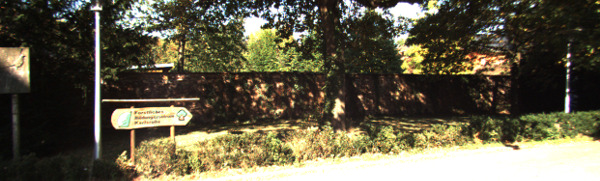
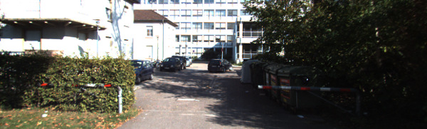
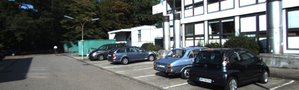
Fig. 9: RGB images of the dataset where vehicles had lower RTI.
discarded all non-frontal data), the framework was able to
framework is the use of Configuration Space instead of the
flag the road segments where the vehicle faced the most
more conventional ambient space for traversability analysis.
difficulty (tight turns). In Frame 90, we were able to discover
This allows for extension to more complicated scenarios in
unexpected features (such as the traversability of the smaller
which higher dimensional state-space based traversability can
vehicle under the road barrier). Much of this is not possible
be explored, where by state we mean the incorporation of
in framework that measures road conditions without referring
vehicle kinematics (e.g. speed) and road surface conditions
to a particular vehicle. Video includes pointcloud and RGB
(e.g. roughness) on top of geometric approach.
images along with RTI for each frame.
[1] Syed Muhammad Abbas, Abubakr Muhammad, Syed Atif Mehdi, and
Karsten Berns. Improvements in accuracy of single camera terrain
classification. In 16th International Conference on Advanced Robotics(ICAR), 2013, pages 1–6. IEEE, 2013.
[2] Mauro Bellone, Giulio Reina, Nicola I Giannoccaro, and Luigi Spedi-
cato. Unevenness point descriptor for terrain analysis in mobile robot
applications. Int Journal Advanced Robotic Sys, 2013.
Vibration-based terrain analysis for mobile robots.
and Automation, 2005. ICRA 2005. Proceedings of the 2005 IEEE
Pointcloud Frames
International Conference on, pages 3415–3420. IEEE, 2005.
[4] Howie M Choset. Principles of robot motion: theory, algorithms, and
Fig. 10: RTI of KITTI dataset.
implementation. MIT press, 2005.
[5] M. Freese E. Rohmer, S. P. N. Singh. V-rep: a versatile and scalable
robot simulation framework. In Proc. of The International Conference
on Intelligent Robots and Systems (IROS), 2013.
ISCUSSION AND CONCLUSIONS
[6] Paul Filitchkin and Katie Byl. Feature-based terrain classification for
We have established a framework under which road
littledog. In Intelligent Robots and Systems (IROS), 2012 IEEE/RSJ
traversability questions can be answered for a given type
International Conference on, pages 1387–1392. IEEE, 2012.
[7] Andreas Geiger, Philip Lenz, Christoph Stiller, and Raquel Urtasun.
of vehicle and exact road conditions. We use standard robot
Vision meets robotics: The kitti dataset.
International Journal of
motion planning techniques to generate a graphical repre-
Robotics Research (IJRR), 2013.
sentation (roadmaps) for the vehicle configuration space. We
[8] Jean-Francois Lalonde, Nicolas Vandapel, Daniel F Huber, and Martial
Hebert. Natural terrain classification using three-dimensional ladar
then use network properties of roadmaps for traversability
data for ground robot mobility. Journal of field robotics, 23(10):839–
analysis of a vehicle on a road surface. With vehicle parame-
ters like width, length, height, wheelbase, track and tire width
[9] Ilkka M Leppänen, Petri J Virekoski, and Aarne J Halme. Sensing
terrain parameters and the characteristics of vehicle-terrain interaction
exactly specified, we can analyze road traversability for that
using the multimode locomotion system of a robot.
vehicle and find how safe it would be for the vehicle to drive
Robots and Systems, 2008. IROS 2008. IEEE/RSJ International Con-
on that road. We have used Maxflow/Mincut and connected
ference on, pages 500–505. IEEE, 2008.
[10] Roberto Manduchi, Andres Castano, Ashit Talukder, and Larry
component analysis to develop a metric which provides
Matthies. Obstacle detection and terrain classification for autonomous
acceptable results to find the narrow passages in road. The
off-road navigation. Autonomous robots, 18(1):81–102, 2005.
results of simulated and experiments on acquired real data
[11] Matthew W McDaniel, Takayuki Nishihata, Christopher A Brooks,
Phil Salesses, and Karl Iagnemma. Terrain classification and iden-
indicate that our RTI can really predict the traversability of
tification of tree stems using ground-based lidar. Journal of Field
any road surface for any vehicle with given parameters.
Robotics, 29(6):891–910, 2012.
An advantage of using RTI is that we can find the
[12] V Molino, R Madhavan, E Messina, T Downs, A Jacoff, and S Bal-
akirsky. Traversability metrics for urban search and rescue robots on
traversability of any vehicle using 3D point cloud of any
rough terrain. Proceedings of the Performance Metrics for Intelligent
road. With the rise of autonomous vehicles, it is easier than
Systems, 2006.
ever to get 3D maps of the roads. Once a 3D map is available,
[13] Mohammad Norouzi, Jaime Valls Miro, and Gamini Dissanayake.
Planning high-visibility stable paths for reconfigurable robots on
we can perform traversability analysis to get RTI of the
uneven terrain.
In Intelligent Robots and Systems (IROS), 2012
road surface and use it for various tasks. As shown, only
IEEE/RSJ International Conference on, pages 2844–2849. IEEE, 2012.
the number of obstacles or the area obstructed by obstacle
[14] Nicolas Vandapel, Raghavendra Rao Donamukkala, and Martial
Hebert. Unmanned ground vehicle navigation using aerial ladar data.
is not enough to determine whether it is less safer than the
The International Journal of Robotics Research, 25(1):31–51, 2006.
another road with less obstacles. RTI could help us find safestroutes for vehicles to travel on. An important aspect of our
Source: https://cyphynets.lums.edu.pk/images/RTI-IROS2016.pdf
Published Ahead of Print on March 8, 2010 as 10.1200/JCO.2009.24.4798 JOURNAL OF CLINICAL ONCOLOGY Prediction of Risk of Distant Recurrence Using the 21-GeneRecurrence Score in Node-Negative and Node-PositivePostmenopausal Patients With Breast Cancer Treated WithAnastrozole or Tamoxifen: A TransATAC StudyMitch Dowsett, Jack Cuzick, Christopher Wale, John Forbes, Elizabeth A. Mallon, Janine Salter, Emma Quinn,Anita Dunbier, Michael Baum, Aman Buzdar, Anthony Howell, Roberto Bugarini, Frederick L. Baehner,and Steven Shak
Original Article Dermatological side effects of Sildenafil among a group of Iraqi males Nadheer A. Matloob Dermatological Side Effects of Sildenafil among a group of Iraqi Nadheer A. Matloob* MBCHB, DDV, FICMS, CABD Summary: Background: Sildenafil is a drug that is used to treat erectile dysfunctions, it acts by inhibiting CGMP specific phosphodiesterase type 5, an enzyme that regulates blood flow in the penis. The most common adverse effects of sildenafil are headache, dyspepsia, nasal congestion and impaired vision which includes photophobia and blurred vision. Many dermatological side effects are present like flushing,


